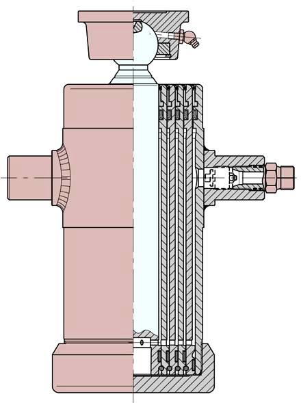
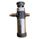
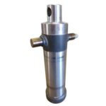
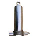
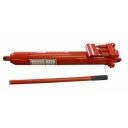
Aline Trading P/L present a range of quality made multi stage hydraulic cylinders designed for use on tipping trailers, ute’s and many other applications.
Our cylinders are made from hot-rolled tubes (without welding), having a maximum tensile stress R= N/mm2 590, yield point Rs= N/mm2 460. The last extension, on the contrary, in C 40 hot-rolled. The pressed cap and bottom disc are made with Fe 50 hot-pressed.
The external surface of all the extensions have a chromium-plated film applied with an approximate thickness of mm. 0,010 – 0,015, with a medium superficial ruggedness Ra= 0, 15- 0, 20.
The extension guide is secured by delrin rings, for both the external and internal sliding.
The seals used are highly resistant to permanent deformation and wear, with a working temperature from -40 Deg to +110 Deg C.
It is recommended, for better functioning and durability of the cylinder itself, to use hydraulic mineral oils and mount appropriate filters to prevent the possibility of infiltration of impurities inside the cylinder.
Rated pressure 160 Bar reaching maximum point of 180 Bar.
Absolutely avoid the cylinders reaching the end of their stroke and touching the body when in rest position. Over extending of the cylinders should be prevented by use of a physical, electric or hydraulic limiting device. Characteristics and dimensions are not binding.
Note: Sizes listed herin are our normal stocked range. Other sizes are available against volume OEM orders.
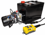
PRODUCT SPECS & PHOTOS
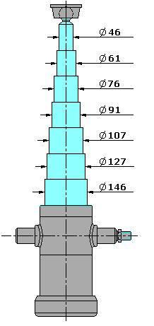
Thrust in Kilograms for single extension
Rated pressure 160 Bar reaching maximum point of 180 Bar.
Pressure (Bar)
46
61
76
91
107
127
146
100
1.660
2.920
4.530
6.500
8.980
12.660
16.730
125
2.070
3.650
5.660
8.120
11.230
15.820
20.910
160
2.650
4.670
7.250
10.400
14.370
20.250
26.770
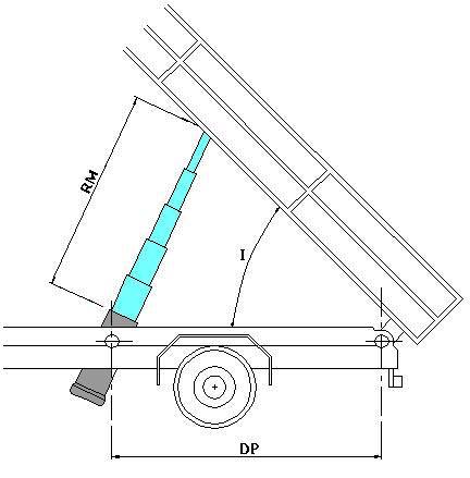
Body tilting tables.
RM = Jack stroke.
DP = Distance between pins in mm
I = Box tilting.
Note: Make sure that the cylinder does not bottom or top out and the box does not rest on it when in the home position.
Body tilting table based on the distance between pins and cylinder stroke.